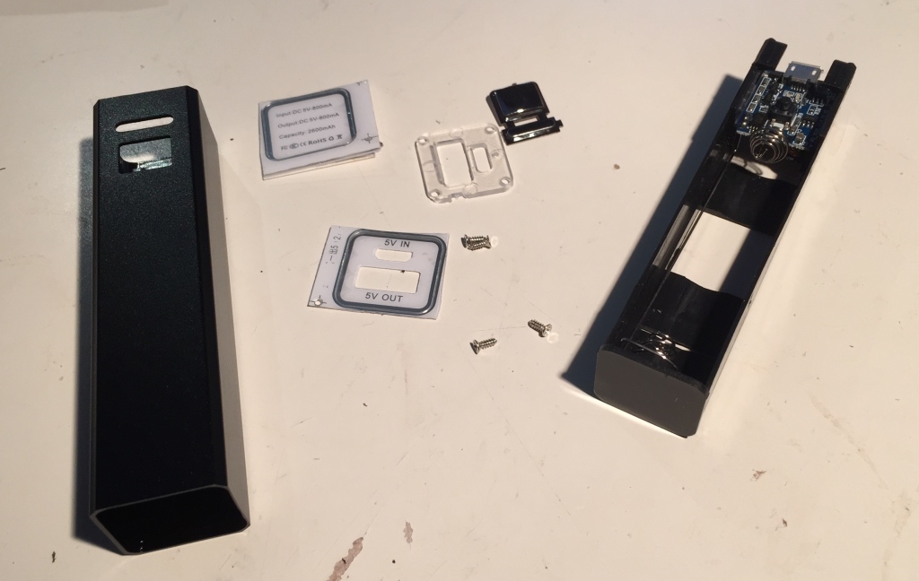
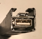
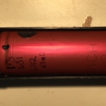
I just received some cheap DIY single 18650 cell USB power bank kits from Bangood. The listing itself doesn’t have any specifics about the current ratings on the devices, but an endcap for case says that it supports 800mA input and output.
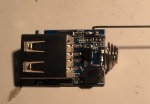
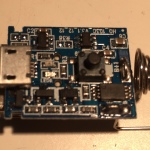
I was going to do a teardown, but I didn’t have much luck identifying the key components.
Fortunately, someone else had more luck when they tore down a very similar device with a cell pre-installed they received as part of a promotion from DigiKey. A comment on their post filled out the remaining details. The device I acquired differs in a few respects, including the PCB layout, but it appears that the key ICs are identical.
- DW03D – Battery management IC by Shenzhen Fuman Electronics Co. This provides protection from over-discharge, overcharge, and excessive discharge currents.
- B628 – 2A boost converter contoller, probably the XRT1151 by Xysemi.
- LTC4054 – Linear lithium-ion battery charge controller IC by Linear Technology
I bought these kits because I’d like to turn repurposed 18650 cells from laptop battery packs into a useful, inexpensive gift/give-away. Ideally, I wanted something with a 1A output, but I figured that for under $2.40 each for 3 or more these were worth a closer look.
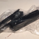
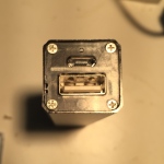
First impressions are roughly what I expected from the photos on the product listing. The case is finished extruded aluminum. The guts are held together with a flimsy plastic insert. Assembly is simple. Once the cell is in place, you slip a metal-coated plastic button into the case so it rests in a cut in the aluminum shell, and slid the subassembly with the cell and electronics in from the bottom of the tube. Its fixed in place by putting plastic endcap at the top and screwing it to the plastic insert with 4 small screws. To finish, you apply adhesive-backed trim pieces with thick polyurethane coating to cover the screws and the bottom.
Tests
Performance Overview
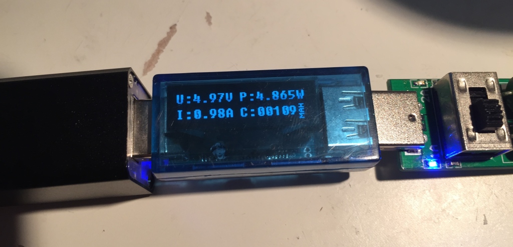 To test the power output, I used a Samsung cell I’d recovered from an old but unused Acer laptop pack. The cell was originally rated at 2,600 mAh capacity, but when tested in an analyzing charger, it has had ~2,500 mAh capacity. The powerbank was able to deliver ~0.9A at about 4.9v. In a test with a similar cell, a second example of the same product did slightly better, providing ~1A at 5V.
Input Voltage
Low Voltage Protection
With a 1A (5 Ohm) USB load, the powerbank’s cell discharge protection cut in at about 3v on two samples. Once the protection cuts in the powerbank will not switch on again, even after the cell voltage rebounds, until power is applied to the charging input.
Current Draw
Next I looked at the performance device in more detail. In order to provide 5V to the USB port from a lithium ion cell whose voltage varies between 3 – 4.2v, USB power banks use a boost converter. A boost converter effectively trades current for voltage. To deliver 1A at 5v from a 3.7v battery, a perfectly efficient boost converter would need to draw 5v/3.7v * 1A = 1.35A. Real boost converters aren’t perfectly efficient, and their efficiency also varies over the range of input voltages.
For my tests, I used a bench power supply as the current source, in place of a lithium ion cell. This allowed me to quickly test across the range of voltages delivered during the discharge of a lithium ion cell. Testing with a real cell would have taken an hour or more. I applied the voltage near the cell contacts so the resistance of the wiring inside the power bank would be factored in.
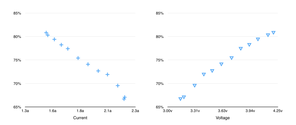
Efficiency
Efficiency was calculated as the input power (V * I) vs USB output power. When tested using a bench power supply in place of a cell, the best-case efficiency was ~80% @ 4.2v requiring about 1.5A input, dropping to ~65% at 3V, requiring 2.2A. This isn’t very good.
In the course of testing the efficiency, I noticed some other interesting characteristics.
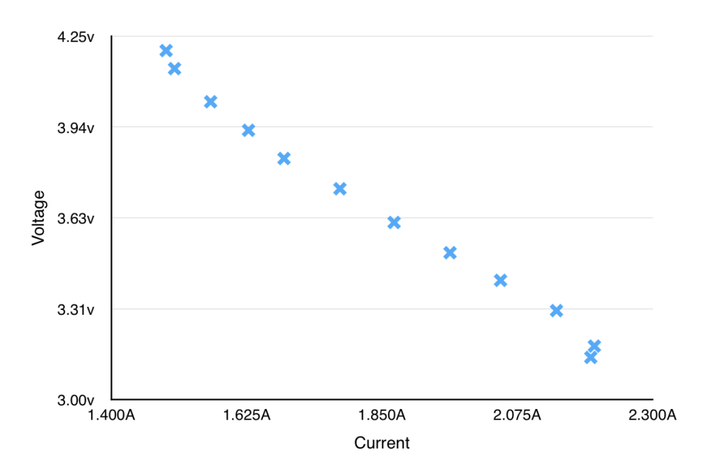
The voltage of the USB output held at a steady 5v under load until the supply voltage hit ~3.4v. The current draw at this point was ~2A. The output voltage then declined, hitting ~4.75v and falling out of USB spec when the supply voltage hit about 3.23v. At this point, supply current was about 2.2A. The delivered voltage continued to decline until the device’s protection circuitry intervened and cut off the output at a supplied voltage of ~3.2V, which is a bit premature.
Given the currents involved, I suspected that the premature cut-off was the result of a voltage drop over the rather thin leads between the PCB and the battery terminal. When I investigated, I found that the voltage dropped by 0.17v at 2.2A over a 65mm length of the negative lead. Which wasted ~5% of the batteries power, and probably left ~10% of the useable capacity untapped.
Battery Lead Retrofit and Results
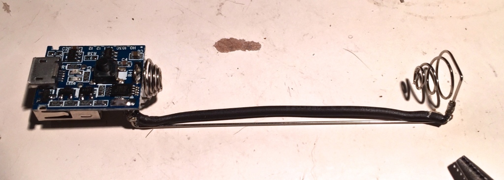
I retrofitted the device by soldering a lead to lower the resistance over the negative conductor. This modification resulted in considerable improvements. The voltage drop decreaced by an order of magnitude to about 0.01v. This had other important results. The discharge protection doesn’t cut in until ~3.0v, allowing more of the cell capacity to be utilized. The power loss before the buck converter is also reduced, increasing the efficiency of the device, and reducing the current draw required across the cell voltage range. This allows the device to maintain the voltage at the USB output longer, it remains at 5v until supply voltage is about 3.3v, and remains within USB spec until the cell discharge protection cuts in at 3v.
Overall efficiency with the bypass in place improves slightly, ranging from 82% down to 70%. Using a cell as the power source, overall efficiency through a full discharge cycle is still pretty poor, coming in at ~68%.
The conversion efficiency is a problem, but this device has a bigger problem which became obvious when I looked at the charging performance.
While I was happy to find that the output can deliver more than the 800mA listed on the label, I found that the input seems to fall far short of the listed 800mA input. I’m seeing a current draw of only ~420mA during charging with both samples I’ve tested.
There is a bigger issue than the slow charging though. I monitored cell voltage during the charging cycle and found that charging terminates prematurely. In one sample, charging was terminated at 4.08v, and the other, 4.1v. Through monitoring with a USB meter, I found that both examples draw about 2000mAh of current. Since the charge controller is linear, and because lithium charing is coulomb efficient, this is a good estimate of the current drained from and returned to a cell during the charge cycle. The cells I used for the tests measure in at about 2,500 mAh capacity, which means that the device is wasting ~20% of the capacity of the cell. The impact on useable power capacity is even greater, since the unused capacity is at the highest end of the voltage range, where the conversion is most efficient.
Conclusion
This power bank has a great price and a nice case, but the insides make it unacceptable. As shipped, it makes bad use of good recycled cells. This situation can be improved significantly by a simple modification to the connection between the cell and the PCB, but premature charge termination means >20% of cell capacity is un-utilized.
More Info
- Julian Ilet’s video review and follow-up (thanks to WarHawk-AVG on the Budget Light Forum for the pointer)
- CLDCPU’s teardown
Awesome review and mod!
I am almost tempted to go ahead and scuff the negative on my batteries and quickly solder a 22ga wire on them instead of using those cheap thin aluminum connectors. A real fast hit with a soldering iron w/ plenty of flux and it barely heats up the battery before bonding.
Thanks!.
I know what you mean about trying solder.
I’ve been thinking of trying to get a community project going to come up with a foolproof design for a DIY battery spot welder for building bigger packs. In the meantime, for one or two cells, I might try some solder. With generous pretinning on the wire and plenty of flux it would work pretty well.