I recently received a ZH-YU ZB206+v1.3 Battery Tester from Fasttech. This device can test internal resistance (or, more properly impedance), amp (Ah) and power (Wh) capacity of Lithium ion cells and 2s packs.
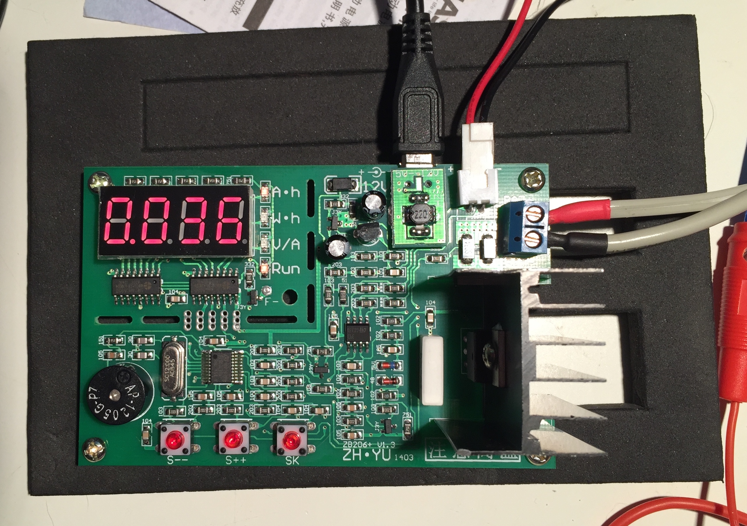
The product is delivered as a bare assembled PCB with a good sized aluminum heatsink sticking out of one side. There are two models available, one that is powered with 12v DC through a barrel connector, and another powered with 5v DC through a micro USB connector. There is a lexan case available for an extra cost.
The product came with a small sheet of paper with chinese instructions printed on once side. With the help of people on the Fasttech and Budget Light forums I was able to find crude translations of the instructions. Which I’m going to reinterpret here:
Capabilities
- Testing Modes
- Discharge testing using 0.1 to 2.6A
- Internal resistance/impedence testing
- Configuration Options
- Discharge current
- Discharge current can be adjusted in 100mA intervals between 0.1 A and 2.6A
- Automatic battery type detection and discharge termination voltage selection.
- In automatic mode, the starting voltage of the battery is used to guess the cell type and configuration in order to select a discharge termination.
- In manual mode, the user sets the termination voltage manually.
- Pulsed vs Continuous test modes
- Pulsed mode temporarily disconnects when reading voltage in order to obtain an measurement without losses due to wire resistance. This is only useful in 2 wire test mode.
- 2 and 4 wire test modes
- In two wire mode, which is the factory default, the test load is applied, the and voltage readings are taken, through the main battery contacts
- In four wire mode, voltage readings are taken through a separate set of contacts that should be wired to the battery separately from the main battery contacts in order to obtain a more precise voltage reading and a more accurate estimate of current and power and detection of the termination point.
- Power limiting.
- By default, the tester will not allow more than 12W of power to be dissipated during a test in order to protect the battery and testing circuits. This limitation can be disabled.
- Fan Control
- Sets the threshold used to switch on and off an optional fan to facilitate cooling of the battery and load.
- Buzzer
- By default, a buzzer attached to the board sounds when the discharge limit voltage is reached. This can be disabled.
- Discharge current
Caution:
The 5v model of the board shouldn’t be powered off a computers USB port because of electrical noise caused by the board’s power conversion circuitry.
Operating Modes
At startup, the device enters one of three operating modes, depending on the control keys pressed when power is first applied.
Discharge Test Mode
Without any keys pressed, the tester starts up in discharge test mode. The user can easily decrease or increase the discharge current using the “S–” and “S++” buttons.
Pressing the “SK” key starts the discharge test. Before discharge begins it will check for error conditions and display an error code if any exist. Otherwise, it will briefly display the discharge termination voltage before commencing the discharge test.
During the discharge test, the “Run” LED will be lit. In addition, the Ah, Wh, and V/A LEDs will each cycle on and off in a repeating sequence. These LEDs indicate what value is currently being displayed on the multi-segment numeric LED display.
During the discharge test, you can temporarily stop the test by pressing the “S++” button. The current test progress will be retained, and the test can be continued by pressing the “SK” button. Pressing the “S–” button will stop the test and clear the test progress.
When the termination voltage is reached, the discharge test will stop, the buzzer will sound, and the display will display the final current discharge reading. Pressing “SK” once will silence the alarm. Pressing the “S–” or “S++” buttons will switch between displaying the Ah, Wh, and discharge plateau voltage.
Resistance Test Mode
This mode is probably more accurately called Impedence test mode
If the “S–” button is held down when power is applied to the tester, it will enter resistance testing mode. Resistance testing mode only works with a four wire test connection, and requires that the batteries being tested are charged to at least 10% capacity.
In resistance testing mode, the tester continuously updates the display to show the # of mOhm resistance of the connected cell. The “SK” button can be pressed to switch the display to the voltage of the connected cell, and again to return to displaying the resistance.
In order to exit resistance test mode, power must be removed and reconnected.
Configuration Mode
If the “SK” is held down when power is applied to the tester, it will enter configuration mode. The configuration settings accessible through this mode are summarized above in the capabilities section.
In configuration mode, pressing “SK” switches to the next setting, and pressing “S–” and “S++” switches between the available options for the setting.
The settings and options are as follows:
Test Connection Mode:
“LJ2” is two-wire test mode, “LJ4” is four-wire test mode.
Automatic battery recognition mode:
“Auon” enables the automatic termination voltage detection feature. “AuOF” disables it, and allows it to be set manually after setting the discharge current in discharge testing mode.
Beeper
“bEon” enables the audible alarm when discharge termination current is reached. “bEoF” disables it.
Power Limit
“LPon” enables the power limit. “LPoF” disables it. Disabling the power limit may damage the battery or the tester, and should only be used when additional cooling, such as a fan, or additional heatsink, is used.
Fan Control
“SF00” – “SF10” the discharge wattage at which the fan is powered. SF00 enables the fan whenever the discharge test is running. SF05 only enables it at or above 5W power dissapation, SF10 at or above 10W power dissipation, etc.
Pressing “SK” again will exit configuration mode and enter discharge testing mode.
Discharge Test Mode with Manual Termination Voltage Setting.
When the automatic battery recognition feature is disabled in configuration mode, the operator can adjust the discharge termination voltage in discharge testing mode.
It works as described above, with the following addition: After selecting the discharge current as described above, pressing the “SK” button will switch the display to show the test measurement mode and termination voltage.
If 4 wire test connection is set in Configuration Mode, the first position in the display will contain a “P,” if 2 wire test mode is set, it will display a “b”.
The remaining positions show the test termination voltage, which can be adjusted using the S– and S++ buttons between 1 and 6v in 0.1v increments.
Pressing “SK” again will initiate the discharge test.
Calibration Mode
It is possible to calibrate the tester by invoking its calibration mode. I haven’t tried this yet, and so I haven’t tried to rewrite the instructions.
Other Documentation
Machine translations of the documentation are available:
Teardown
There isn’t much to tear down, since it came as a board.
I’ll update this section though with a list of key components.
Testing Results / Observations
Capacity measurements on two fully charged Samsung ICR18650-26C cells at 2.6A discharge rate were within 5% of the capacity measured on a Opus BT-C3100 v2 charger at much lower current.
The cells were discharged to 3.0v, and rebounded to ~3.5v shortly after discharge termination.
During discharge, I used the temperature probe that came with my UT139C multimeter to measure the temperature of the ceramic resistor and power transistor used to provide the load. The ceramic resistor measured 60C and the hottest point on the power transistor, contacting the top of package and the metal tab measured 88C. The thermal contact was sub-optimal so its likely these surfaces were somewhat hotter.
I disabled the power limit, but I was unable to set a discharge current higher than 2.6A. My interpretation is that the power limit only applies when discharging multi-cell packs.
Resistance testing registered ~60 mOhm for each cell. These readings are somewhat lower than the ~140 mOhm values obtained from my Opus charger, which isn’t generally regarded for its resistance testing precision. I don’t currently have another way of measuring cell resistance to use as a basis of comparison.
Conclusions
TBD
Hello,
a question, i read “Fan Control”, but where i can connect the Fan?
I have the 12V model.
thanks
Danny
I haven’t tried the fan control feature myself, but, there is hole (it is filled with solder on mine) labeled “F-” right below the “Run” LED. You’d connect the negative lead from a 12V fan there. I don’t have the 12v version, but you should be able to tie into the positive line from the power connection somehow. On the 5v, I think there is a little solder pad on top of the 5v adapter PCB that I think is to provide +5v for the fan.
Honestly though, I’m not sure I’d mess around with the fan control. If I were using a fan, I’d probably just power it directly and run it all the time. If it was too noisy, I’d use some resistors or something to drop the voltage and speed.
Hope that helps. Feel free to start a thread in the forum if you have more questions, or to share how you got things hooked-up.
What is the lowest termination voltage one can set in AuOF mode?
I want to measure AA batteries and want to terminate at 0.8V or 0.9V. Can ZB206+ do that?
I just re-read your article and found the answer: the termination voltage in AuOF mode can be set between 1 and 6v in 0.1v increments. So no, 0.8V or 0.9V is not possible with ZB206+.
Hi
Any recommendation about the wires used.
Seems like the two sets of wires used are different. Thank you
http://www.offerany.com/p-37631081190.html
Aquí verán como se conecta un ventilador. Correcto es “F”.
Gracias por el manual tenia serias dudas sobre tema impedancia o resistencia interna.
Un cordial saludo.
Thanks very much, you have saved me much research.
When the tester is in discharge process and if it is suddenly powered off, tester will automatically save the current setting numerical value, working state, and test result; power up the tester with DC12V again and the tester will automatically restore discharge process.
For 4 wire testing mode it is possible to just solder extra two wires to a classic battery holder?
https://img2.banggood.com/thumb/view/2014/xiemeijuan/04/SKU217886/IMG_5064.jpg
…or it must be separate from the current wire?
Adding extra wires will help by eliminating voltage drop in the current leads from the voltage measurement. It will still leave the drop due to the resistance of the test clip itself and the contact resistance, but it’ll still improve the accuracy.
You might want to just use the existing leads as sense leads and solder thicker wire and use that for the current leads.
Where can the case be purchased
Regards,
Mike
Hi
Thanks a trillion for the instructions, really appreciate it.
I have the 12V one and I have a question about setting the cut-off voltage:
.- I have entered the Configuration mode
.- Set AuOF
then put a battery in, push SK to get started and then I get “asked” the cutoff voltage but there are like 2 groups/options (both go from 12V to 6V) “b” and”p”.
So I can set “b1.0v” to “b6.0v” or “p1.0v” to “p6.0v”
Do you know the difference between the prefixes “b” and “p”?
Many thanks in advance
The prefixes B and P are explained in the text above, under the section “Discharge Test Mode with Manual Termination Voltage Setting.” You should only get one choice (P if 4-wire is set, B if 2-wire). So, you need to set the Mode 2LJ or 4 LJ in config – mine is set to 4-wire and I only get shown P1.0V to P6.0V