This page will be updated when I have new information
2014-08-27 Review section added with voltage/current measurements and overall impressions of product.
2014-08-31 Added max cell length
2014-12-04 Updated max current delivery upward to reflect the results of new tests with different testing equipment. Also added note about overheating cut-out under >2A load.
2014-12-09 Updated to reflect that both ports use the Apple standard to signal that devices may draw up to 2A.
Overview
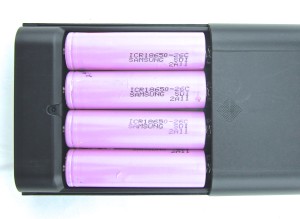
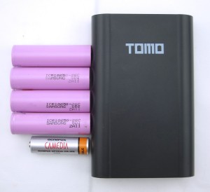 I’ve been using a Tomo V8-4 power bank, or USB charger, filled with four 2600mAh Samsung 18650 cells I scavenged from a cheap, unused, laptop battery, to charge my iPhone and iPad when I’m low on juice and away from a power outlet.
There are cheaper four-cell DIY USB power banks available. I chose the Tomo V8 because it reports the charge level, and manages charge and discharge of each cell separately, which is useful for scavenged cells. The same product is available as the Soshine E3. There is also two-cell versions called the Tomo V8-2.

Review & Testing
The TOMO V8-4 power bank feels solid and well made, but it doesn’t feel like a premium product. The volume is large enough to hold ~8 cells, rather than four, which may be an issue if you are space constrained. The weight though, is reasonable. It fits four 18650 cells. I estimate that it can take cells up to 68.5mm length, and probably 69mm.
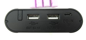
The power bank is turned on by pressing a button on the back, next to one of the USB outputs. It also powers itself up automatically when when a USB device or charger is connected.
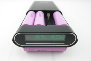
When powered on, the display indicates the approximate level of charge of each individual cell.
USB Power Output
When powering USB devices, the right-hand side of the display indicates which port(s) are drawing current. The representation of each port has an animated indicator line that sweeps from left to right to indicate current flow. It isn’t clear to me whether or not the speed of the animation hints at actual current.
I’ve had some challenges when trying to measure current delivery to USB devices.
When used with a resistive 5 or 2.5 Ohm load, which should draw 1 or 2 A, respectively, at USB voltages (5V), the powerbank delivers current, but behaves strangely. The display shows intermittent or non-existent current draw through the port the load is connected to, and will power itself down after a time-out period as if nothing was connected.
When the load is connected to the 2A output though a USB voltage and current meter, it shows a draw of ~0.95A @4.88V with a 5 Ohm load and ~1.9A @ 4.8V with a 2.5 Ohm load.
On the 1A output, though a USB voltage and current meter, it also shows ~0.95A @ 4.88V with a 5 Ohm load. With a 2.5 Ohm load, it cuts the output and the display shows a fault condition in the 1A port.
With both ports, in use, it seems to be able to deliver a combined 2.5A without too much voltage drop, but after 5 minutes or so, it cuts out. The display backlight goes black, but the display remains powered and shows that the cells have ~50% charge. The cutout seems to be due to overheating, because it automatically resumes after a few minutes.
The bottom line seems to be that the TOMO V8-4 can provide USB devices over 2A of current at USB voltages from its internal batteries. It signals iOS devices that they can draw over up to 2A of current.
The powerbank shuts itself off when all the cells drop to ~3V.
USB Charge Rate Signalling
When connected to a computer, USB devices must go through a negotiation procedure before they can draw more than 500mA power. In order to safely provide higher charging currents using a “dumb” wall adapter, Apple created a simpler signaling mechanism for the iPod, which they further adapted for the iPhone and iPad.
Some device makers imitated Apple’s approach to maximize compatibility of their devices with chargers designed for Apple devices. However, more recently, a USB charging standard was created and has been adopted by most device makers other than Apple.
When I used the TOMO power bank to charge iOS devices while using a USB meter to check the charging current, I had confusing, inconsistent results, I decided to take a closer look at the charge rate signaling used by the USB ports. I found that both ports signal that an Apple device can draw up to 2A of current. This could cause a problem, because the port labeled as 1A will turn off the power output if a device draws 2A.
I do not know how non-Apple devices will behave when charged from the Tomo.
USB Power Input / Battery Charging
When charging, the cells being charged are animated to show that they are receiving current. The speed of the animation doesn’t seem to give any indication of the current charging current or voltage, it either runs, or it doesn’t.
The Tomo V8-4 can recharge cells while also powering USB devices, provided the USB device current draw isn’t too high. When the USB devices draw in excess of ~700 mAh, the power bank stops charging and just powers the external USB devices until they are disconnected or stop drawing current.
The largest current-draw I’ve observed when charging 4 cells is ~1.5A, 25% less than the max charging capability of the charge controller ICs (see below).
The charging section seems to operate appropriately in that current is reduced once the cells reach their target voltage and charging is stopped once the charging current drops off significantly, and doesn’t begin again until the cells are discharged to ~4V. So, it approximates appropriate Li-Ion battery behavior, but I can’t say how precisely.
I’ve observed that the two slots on the left charge the the idea 4.2V level, while the two on the right only charge to ~4.16-4.17V. This is within the 1% error on the datasheet for the charger ICs, but the grouping seems strange, particularly since someone else reports a similar pattern with their TOMO V8-4 powerbank.
Conclusion
I really wanted to love this power bank, but it comes up a little short.
The good:
- Charges and discharges each cell independently
- Protects cells against over-discharge and incorrect insertion (reverse polarity).
- Respectable charging behavior, doesn’t overcharge cells.
- Attractive design and solidly made
The not so good:
- Doesn’t charge iOS devices at their maximum rate.
- Leisurely charge rate for 18650 cells (~300-400 mA, max)
- Capable dot-matrix display isn’t used to its full potential. Would be useful to give numeric estimates of voltages and currents.
- Variable charge levels due to design or manufacturing issues.
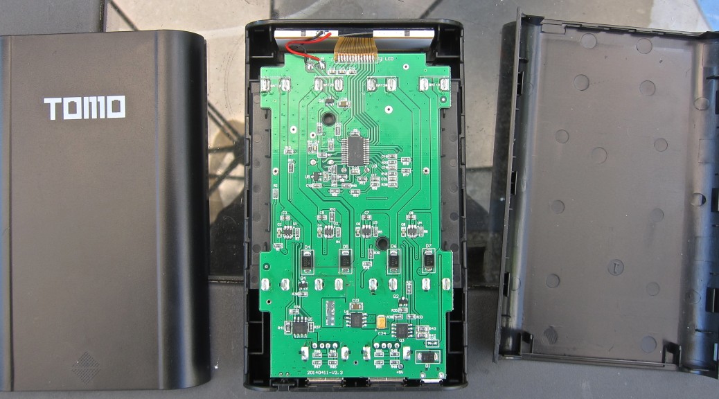
Teardown
After using it for a while, I decided I wanted to know what was inside. The case design is quite elegant. It feels solid, and yet it is easily disassembled without a screwdriver. I used a small plastic lever to “derail” the sliding cover while I slid it shut. With the cover off, I was able to disengage the bottom of the case from the center section.
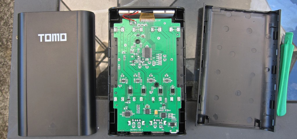
It was easy to slip the LCD display loose from the case. From there I could tip the circuit board out. In order to release it fully, I had to compress the wire springs that formed the negative-contact for the batteries so that they would slip through the openings in the plastic case.
I don’t know about the actual design of the circuits, but the layout of the printed circuit board seemed elegant and straightforward.
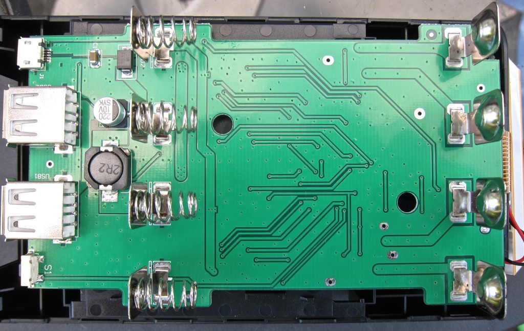
The top side is primarily devoted to circuit routing, and mounting of the USB connectors and battery contacts. There is also a microswitch for turning the unit on and off, an inductor and a large capacitor, presumably for the output power regulation circuit, and a capacitor and an SS32 Schottkey diode from MIC.
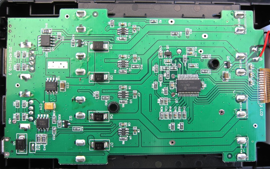
Most of the components are mounted on the bottom-side of the PCB.
Voltage Leveling and Reverse Polarity Protection
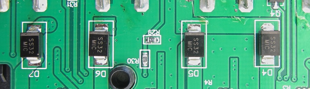
There are four SS32 Schottkey diodes from MIC, each associated with the negative contact for one of the lithium cells.
I think these serve to make sure all the cells maintain a similar voltage level during discharge, and that when cells have dissimilar voltages, there aren’t large currents between them that could damage the cells.
This design mitigates some of the problems with using dissimilar cells in parallel, but not all of them. Depending on their charge levels and voltages, the current demands on cells will vary. Its possible that with a wide enough difference among cells, the highest voltage cell carries the entire load, while the other cells sit idle. Depending on the other accommodations of the design, this could lead to cells being drained at levels in excess of their design limits.
Battery Charging
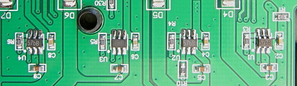
There are also four small, identical 6-pin ICs, each of which appears to be associated with an individual cell. The markings are “57bB.” My assumption, given that their are four of them, and their position in the circuit, is that these are purpose-built Li-ion charging ICs. Based on that, the markings, and the form factor, there are a variety of candidates, but I’m pretty sure they are TP4057s in a SOT-26-3 package from TP Micro.
On paper, at least, these sound like capable charging devices.
- Adjustable charging current up to 500mA
- cv/cc charging profile
- Automatic charge termination at C/10
As noted in the review section, above, as designed/manufactured, the power bank doesn’t seem to be using these to their full potential. Actual charging current seems to be closer to 300 mA.
More information:
- TP4057 Datasheet (full, Chinese)
- TP4057 Datasheet (partial, english) Note: This is for a higher-amperage version in an 8-pin package.
USB Power Output
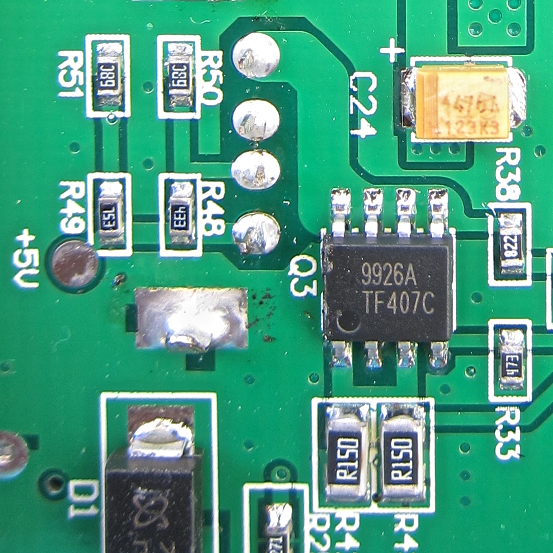
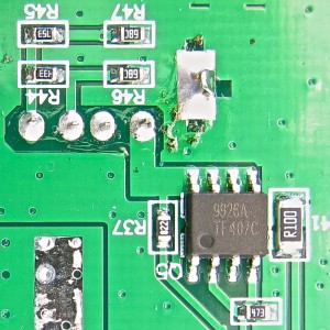
Next, I noticed two identical 8-pin ICs, each associated with one of the two USB ports for powering external devices. They are both marked “9926A TF407C.” The 9926A marking suggests that are dual N-channel MOSFETs, but the exact specifications and origin are unclear. My best guess is that they are made by a mainland Chinese company. I don’t know enough to know exactly what function these serve. My guess is that they switch the output on and off, and might go so far as to regulate output current to manage power distribution when two USB devices are connected.
I haven’t tested this for myself, but from this Russian review on YourTube, it appears that the current limits on the outputs are managed separately.
Switch Mode Power Supply for Output
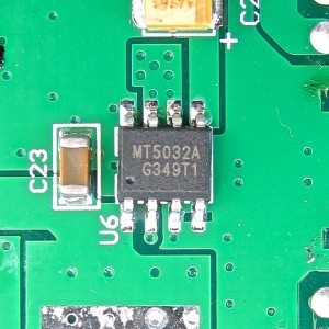
There is another IC that seems associated with the output, a single 8-pin chip. Its marked “MT5032A G349T1,” which unambiguously identifies it as a MT5032 800kHz Synchronous Step-up Converter. This forms the core of a boost converter, which is type of switch-mode power supply. This takes the 3-4.2V provided by the batteries and converts it to the regulated 5V voltage fed to the USB devices.
Some details from the datasheet:
- 2.1A output with a 3V input, at higher input voltages, it can deliver higher currents.
- ~94% efficiency at 500mA output throughout input voltage range
- ~90% average efficiency at 2,000mA output over input voltage range
- Fixed 5.1V output when pin 4 is wired to ground (as it is in this device)
As noted above, this power bank doesn’t seem to approach the theoretical output currents for this device.
The highest current observed has been 2.25 A when passing-through power from a 5V USB power adapter.
More information:
Microcontroller
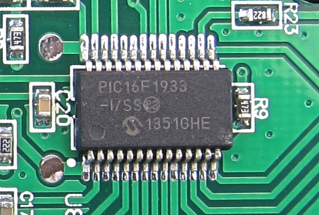
The largest chip is a PIC16F1933 microcontroller. This drives the display, which provides information about whether relative charge-level for each cell, and output through each USB port. When an external USB power source is connected, it also indicates whether or not each cell is being charged.
These functions clearly require that it have a way to read whether current is flowing through each USB port, the voltage for each cell, and whether or not each charging IC is active.
It probably also plays a role in detecting when a device is connected, turning the output ports on or off, and turning the charging ICs on an off. It could even play a role in regulating charging rate, and the distribution of output current between the two ports. I may try to figure these details out in the future, but learning more is going to require some combination of tracing out the circuits in more detail and/or probing voltages during operation.
Very Good PowerBank!
Excellent tear down. Hopefully you’ll do many more! Thank you.
great Review 🙂
If you found a powerbank with volt / current measurements (dot Display) please let it know us 🙂
I got one but mot sure it’s the original. I will have to tear it down a d compare with yours. Mine stops charging et 4.2 v but stops discharging (charging devices) at 3.6 or 3.7v !!! When I get the batteries out after it shuts down i find all batteries are at 3.6 or 3.7 v !!!
When charging the max current draw with charger doctor is 1.5a. When charging the ipad 3 the current ranges between 0.9 and 1.4. I’m using an ipad 3 charger.
One important thing is the small charging cable is required for this tomo charger to draw 1.4 a from the ipad charger. The small cable is also dangerous to use since it does not meet the amp specs And overheats. I had to replace it with a western digital hard drive small usb cable. Don’t leave this charger on with the supplied cable! And don’t use a dumb cable (-/+) as it will only charge at standard usb current around 0.5 amp. The cable should be a good usb cable with the four usb pins i guess. I will have to investigate the discharge limit of 3.7 v. This is probably because of the 18650 batteries I am testing. The came from used laptop batteries. I managed to charge the ipad 3 to 40% off of 4 used sony batteries which have been lying in the basement for about 8 years !!!! I’m also charging 17670 batteries.
Comment just to get notifications
Best powerbank i ve ever seen …
I wonder if someone had already dumped the firmware for it…
That way we could turn it into something more fun, voltage displays and stuff.
Hi all,
i have Soshine E3 and i have a big problem. From the first time i used this PB i have noticed that battery on slot 3 is fully drained(to ~0.5V) when device not in use for a week or two. I have used 3 different sets of batteries (4XSony, 4XSamsung, 4XPanasonic) and all balanced to 0.01V and each time same result – battery on slot 3 over discharged.
Inside are SS34 Schottkey diodes not SS32, anyway i got 4 SS32 diodes for replacement in case this is the cause of a draining…. When charging and when device in use everything seems to be ok – monitoring Voltage and Current on each slot… Right now i am going to set up monitoring system and will see what is going on when device is “OFF”. If anyone have any suggestion…
BR,
Matic
Now i have the results, current on slot 3 when device is in power off mode is min. 5mA constantly and pulsating to 10mA on ~ each second. I will search for schematics did already contact the seller and get beck here with news.
The latest ones (Soshine e3) got new firmware which displays the usb current and usb voltage.
Hi “Anonimous”, do you own this latest E3 charger? If you do i kindly ask you to post some images of this new feature and even more can you send us this new firmware?
I got feedback from Soshine and they confirmed the error but no update or solution to be expected for this E3 series. New PB is expected soon and there will be no problems with the draining as on E3 they said.
I dont think the firmware is upgradable, it looks like this: http://s28.postimg.org/p1dcqq1q5/P_20160131_235252.jpg
Looks like the “ui” is different only when it is powering devices the rest is the same.
Mine does a little overcharge 4.21-4.23v on all ports.
Cnod thank you very much for the information! When you take a look inside of the PB and comparing HW with older revision do you see anything different on PCB overlay? And did you notice any overdraining on any port?
BR, Matic
The PCB version is different, some components have different markings.
Hi-res pic would explain more:
http://postimg.org/image/jmjgw48ct/
I tested the drain with a multimeter:
port 3, 1 cell: 1ma pulsing to about 4-6
port 3, 3 cells: 0.5ma pulsing to 1-1.5
I have a crappy chinese multimeter, so results may wary.
Oh and btw there was something about the “6mah drain per day/week?” written on the box, too bad i threw it out.
Huh, thanks for the img, mine PB HW is the same as on image above in the review. It looks like they have changed some things and something else too…
HW revision on my PCB is 20150503-V2.5
HW revision on your PCB is 20150615-V2.6
so it is different in some way and maybe only to be able to display USB current and the voltage… do not know for sure.
Please let me know one more thing, about the pulsating draining is this going on when the device is “ON” or “OFF”?
I tested when in was “off”.
Ok, that means that draining is still present and in overall is not 6mAh or 50mAh if you want but is a lot more per day. I will install micro switch between cell and the port to prevent draining.
matlc,
Did replacing the SS34 Schottkey diodes with SS32 Schottkey diodes make any difference in the drain issue?
Hello dlong, replacing Schottkey did not solve the problem. Now i will cut the line on PCB on port 3 and install micro-switch for turning on when needed… i know it`s not the best solution but without it the device is useless for me.
Agreed. If the drain was much smaller it would not make a big difference but as is, the drain is too high.
When PCB modified i will post results and some images…
Have any success?
Hi, i will try to modify the device over this weekend. I don`t have much free time but i will try to do my best.
I found there is an official web http://www.tomopowerbank.com
If anyone have tried the 3 bay tomo power bank ? They named it TOMO M3
http://www.tomopowerbank.com/shop/tomo-m3/
I haven’t found any reviews, but, I wonder, with a later released product, if they fixed the high drain during standby mode.
Hi Allen,
I have bought the TOMO M3. It is a very nice little charger and I’ve added it to my laptop case. I’ve had a problem with some other ones that have broken apart easily because I tend to put all my gadgets to some abuse tests apparently. This unit has lasted a couple of months already with no signs of damage, despite being dropped and otherwise misused. It’s also the one that I stick in my shirt pocket when going through the airport because it fits so well and is just the right shape. Also you can use the 10% off code(FRIEND10) if it is your first purchase.
Hi, it is me again and just to let you know i`m still working on this project it`s just a lack of time keeping me on a distance from it. By the way i have saved schematics http://shrani.si/f/G/13l/41eFUNyj/soshine-e3.jpg from DX page(review) for Tomo power bank which is no longer available as there is no review at all… a bit strange. I will try to solve this problem by replacing crucial part on a PCB and if not success i will go on with micro switch.
I just bought the Tomo V8-2 and my first use, it only charged my Samsung S4 mini to about 29-30%. This was with some UltraFire 18650 batteries rated at 3000mAh. My testing makes me think they are actually only 2000mAh. I had a USB Volt/Amp meter between the V8-2 and the phone with the best USB cable I have ever tested, and the meter only measured less than 700mA passing through it before the charger cut off. I took about the batteries and measured them at 3.6+V. Anyone figure out why the new power banks are cutting off at this voltage? I measured each battery before install and they where at 4.04-5V each, after sitting around and balancing for weeks after being charged. Any ideas here?
I agree with Dlong, I think your batteries are probably junk, worse than even 2000mAh.
The fact that they were at ~3.6v after the charger shut down suggests that they were pretty much drained.
As for the charging current, what does your phone pull when using other sources? I don’t have any android experience, but from a little googling, it looks like that phone may need some special “signaling” to draw more than 700mA. With iOS devices I found that some USB meters interfered with the phone properly reading the charger/powerbank.
First thoughts:
* I hope you mean 4.04 – 4.05 volt and not 5+ volts. Anything higher than 4.2 volts is too high (in general).
* Ultrafire batteries are known to be bad/recycled/old and outright lie about mAh. See https://www.youtube.com/watch?v=eOshOXcSkDA
* If you have an analyzing battery charger, use it to determine real mAh of battery.
* Measure voltage under load (while it in use). Old batteries don’t hold voltage under load.
I see in the schematic that it is not possible that it drains always from a specific slot. Instead, it will drain from the battery with the highest voltage, as only the associated diode will conduct.
The drain is because the PIC uC is permanently powered through the linear 2v5 regulator (U5). I would have to investigate the expected minimum current drawn to know what would be the minimum, but I guess it could be much smaller if the firmware keeps the PIC in standby by a larger time ratio while waiting for load or power in (less frequent and maybe more efficient polling).
So, as long as the firmware is not improved, if someone wants to place a switch to avoid the battery draining when unused, do not insert it in series with a specific cell, but in the connection from D4…D7 kathodes and C23 to the buck converter (U6 pin 1, L1, U5).
A switch placed in that point will stop the excesive leak. Then the drain will only be about 60-100 uA per cell, through the voltage sensing dividers.
The firmware can not be field upgraded. If eventually fixed, only newer units will have the fixed version.
Jose on a HW revision 20150503-V2.5 drain is always present only on 3 port no matter how high is the cell voltage. I did the test again as i was not 100% sure about replacing the cells between the ports.
I guess that I will buy one, planning to insert a switch if the current draining issue is not fixed yet. I plan to buy the 2 slot version, and I will comment again with any news.
Hi Jose,
thank you for the contribution with this situation we have… I will try to put cell with highest voltage to some other port then 3 port to see if that is the case… as i remember when i put pack of cells to PB(several times) it has always drained the cell at 3rd port. I also believe that this case is related to uC and is not possible to be solved other way then use of microswitch. When i put my kids to sleep i will try to do the test and get back here to report.
Jose,
Yes, please let us know if the 2 slot fixed the firmware or not. Thx.
SavageBull,
I just re-read some of the comments and it seems that Joe (http://powercartel.com/teardowns/tomo-v8-4-soshine-e3-diy-usb-power-bank-teardown/#comment-2518) has the same 3.6/3.7 cut off issue as yours. I wonder what Joe’s and your’s hardware revision is compared to the others.
So far I see
20140411-V.2.3 (Tomo v8-4)
20150503-V2.5 (Soshine E3)
20150615-V2.6
There seems to be a number of changes between 2.6 and 2.3:
These things are missing or moved to other side of the board or location (or I just missed it):
D1
R25 (moved ?)
R21 (moved ?)
D4-D7, SS32 replaced with SS34
C21
And of course, firmware changes are not visible…
TOMO or Soshine has 3.5/3.6 cut off due to new version TOMO/Soshine use wrong U5 chip. Need to use 2.2v or 2.5v version of U5 instead of 3.0v version. Here full description. Use a translator, text in Russian.
http://forum.fonarevka.ru/showthread.php?p=883114#post883114
So, what version I should buy to get lowest possible cut off?
Look at photos of TOMO v8-2 20160102_V2.2
https://goo.gl/photos/QavZrv8B3ycby5918
My E3 v2.6 cuts off exactly at 3.0v, be sure to measure the cutoff under load, especially for worn cells, they tend to sag under load, then bounce back to 3.6v after cutoff.
Mine doesn’t have significant drain issue, 4.10-4.15v after about 1.5 weeks with 4 10yr old samsung cells (measured 1300 of 2000mah rated).
p.s. Don’t buy “insert_super_duper_word_here”Fire cells, they are used crap, use new ones from sanyo/samsung (they are about 3.5eur each) or used “cherry picked” salvaged cells from laptops, if you have a battery tester.
Thanks for the info!
After multiple cut lines and testings i have came to solution – so far so good. I had to cut line between cell3 and BAT pin on 3 port and installed a micro switch in between. I do not know what exactly did the trick, as i have swap “TP4057” on 3 and 4 port to confirm if IC is faulty but the drain was the same on port3. After many cut lines i came to conclusion that the drain is somehow connected with the TP4057. I did not have enough energy as i was doing this in night time to dig into PCB and compare it with the schematics i have post it… So i will leave this pack of cells in the PB for a week to see what will happen – so far with the micro switch cell 3 remains on a voltage level as other cells in the PB.
I finally received my 2 slots version from Tomo.
The drain is 1.6 mA with peaks of 2.8 mA every second.
The drain is shared from both slots if both batteries have the same voltage, or from the battery with the larger voltage otherwise.
This is not too bad, a single fully charged 2Ah battery will last more than 1000 hours.
Placing a switch where I described earlier solves the drain problem.
If the switch is not placed, do not leave batteries inside with little charge for many days.
My unit charges at 400 mA maximum each battery, and the charging curves are perfect. This is keep input requirement below 1A. The charging current can be easily modified changing 2 resistors, and I will set it up to charge at 800 mA. I will also stick some copper sheet to the 2 charger ICs to avoid any thermal limit.
I will put the switch and change the charging current, but as is it is not bad at all. Overall I consider it a very good product for its price.
I do not know why some found more drain on slot 3 even when the battery in it is not the one with largest voltage. But if that indeed happens, their units do not match the published schematic. Or maybe the diode at slot 3 is much better than the rest, but it would be very strange. Does not make much sense to me anyway, I suggest to make sure it was not due to some mistake in analysis or measurements.
Ah, D4-D7 have a relatively large forward voltage. Changing them with shotckys of lower forward voltage will improve the efficiency and lower the shutdown voltage.
With SS32 or SS34 there is a 12% energy loss only in the diodes.
With PMEG3030EP or VS-30BQ015TRPBF the loss is 9%.
SBR10U45SP5 7.5%.
With smart bypass diodes like SM74611, the loss is less than 1%.
The charger voltage limits in my unit are 4.217 and 4.223 V, luckily very well inside the 1% margin. So the charger is perfect for my needs.
The output is common to both ports, and can deliver in theory up to 2.1A total, it can not deliver 2+1A. Both ports are connected in parallel as one 2.1A, only the current sensing is separate for each port.
The uC senses the current of each port and shut downs the converter (always both ports) when any exceeds its rating. I did not check the current limits for each port nor if the uC checks the sum to be below 2.1A for the maximum combined output. I verified that the 2A port can deliver 1.5A, good for most or all standard BC devices, and the 1A good only for devices known to draw 1A or less.
The charger port identification resistors are set for the proprietary, non standard, Apple approach, and are the same for both ports as 1A ports (which is wrong). I think the reason to identify both as 1A for Apple devices, driving both D+ and D- above VREF, is to achieve compatibility with standard BC1.2 devices, although it is not the standard way to do it (it should be a short between D+ and D-, but the chosen Apple 1A setting should work with most or all BC devices too). For BC devices, it would mean that they can draw up to 1.5A, and that’s why we see up to about 1.4A with most devices, and why these devices (those that can draw more than 1A) do not work well with the port marked as 1A. In theory, it could deliver 2A but only Apple devices would draw it, and will not because the port identifies as 1A port to Apple devices.
The drop in d4…d7 diodes causes the converter to stop working with battery voltage below 3.4..3.5V. With better diodes it could go down to 3.15..3.25V, but only with smart bypass diodes will go down to 3.0 V to exploit the full battery capacity. There are not smart bypass diodes with the similar packaging as the SS32, but probably they could be mounted anyway.
The converter is designed to work with single cell without bypass diode, but here it is used with bypass diodes, that’s the reason for the abnormally high shutdown voltage and efficiency losses.
The theoretical converter efficiency is about 85%, which should be achieved if the inductor used is good enough.
The overall efficiency is much worse though, because the bypass diodes. With smart bypass diodes it could go down to 3.0V and reach about 85% overall efficiency.
Overall, as charger the product is very decent. As power bank, not so much, but could be improved easily to be pretty good only changing the diodes, and placing a switch to avoid the excessive drain when unused.
Hope that helps.
A special USB cable that shorts D+ and D- together will make this battery park appear as a Dedicated Charging Port (DCP), allowing non-Apple devices to draw 2A from it.
I use this cable https://amzn.com/B00IXHC0JG
(Only use this on the 2A port!)
very informative can you plese do a article on sohine e3s
http://www.soshine.com.cn/a674.aspx
and how can we modify unit to use panesonic ncr as they can be disharged till 2.5v unlike others pls
thank you
Bought the TOMO M3 v3.0 a while ago (3 x 18650). It displays battery bars, not voltage. It can’t charge the internal batteries while charging at the same time.
Also had problems with leakage on all battery ports: about 5 mA continuously. Solved the power drain problem with a switch. MOSfet would also be possible though.
It doesn’t use diodes in series with the 18650’s, so the loss problems described by Jose Catena a few posts up are not present in this power bank.
Have a photo of the internals and a teardown.
@TS: if interested in the pic, e-mail me.
Hi,
I see there has been so much fun with this device 🙂
I gave mine as a present a long time ago. It is still working fine.
I see that there is a smaller version available now. I was waiting for it as I like the Xiamoi 10400 mah power bank and this T4 version looks like it, compact. I will get one and report back.
Cheers
by the way any one bought this T4 version? Any feedback?
and I just bought me 4 Panasonic NCR18650GA 3500Mah to go with the T4. I hope it will be worth it 🙂
bought the cells here https://eu.nkon.nl at a good price.
I just hope the T4 does not cut the discharge at 3.7v . 3v would be good even if the cells I’m buying can go down to 2.5v
i got the tomo powerbank T4. It is compact. I like the form fatcor. But this power bank makes a hissing sound as soon as I put the cells in it. The hissing noise does a bit down when it shuts off but never disappears entirely. I contacte the the vendor (http://www.tomopowerbank.com/shop/tomo-t4/) three times but no reply. I don’t know if it is safe to keep using it. I requested a refund via paypal. I guess I’m gonna trash it and get another one. I like the idea of being able to charge it using my iphone cable.
I bought a black M3 which was fine and then got a white one and had the same problem with it hissed all the time. I got a replacement (I only had to pay for postage) but this also hissed. I was doing some test with the white M3 – It charged 2 cells up to 4.2V and one cell up to 4.22V. I then did a discharge test using a USB variable load set to 500mA. All the cells discharged to 2.3V !!! NOT very impressed.
Strangely the hissing M3’s have a lower quiescent current draw than the none-hissing M3, only 2mA rather than 4mA (if ONLY is the right word to use when talking about milli rather than micro amps)
Hi, i follow you since i see these power bank in 2016 and buy one.
it works great but i dont know why at some moment i connect the two ends of the usb cable to the tomo…. so one chip burned out and une battery slot went in short… i blew up one tp4057 and ordered one from aliexpress. After i relplaced it the power bank works fine again so confirmed it is a tp4057 as you guess. I would like to know how it measure the current flow.
Thanks for the report. Glad you were able to fix yours.
For measuring the current flow I’d use one of the inexpensive USB meters, like this one.
I have received today my new TOMO T4 (the smallest version of V8-4) and as I noticed in this thread that you have mastered the V8-4, I was wondering if anyone had any problem with the LCD display. Mine has worked for a couple of hours with no problem at all, charged my mobile phone inside my backpack fully, but after I checked it I noticed that the LCD was lit on but the display shows nothing at all. I would be gratefull if anyone has any advise or clue if this is fixable.
Hello,
my box does not charge the cell phone charge either 2.1 A or 1.2 A. The cells can be charged well.
which component can be the cause.
Thanks
I’ve got a similar TOMO, but it’s shorter, even with 4 batteries. I think it’s a new model.
Testing it i discovered it draws ~10-30mAh from the batteries even if the power bank is off, with no cables connected.
That way, with fully charged 18650 at 4.2v, in 30 days they went to 3.7v.
Don’t know if this is common, but i had another Pineng power bank that did the same thing, but drawing ~80mAh. In 7 days there was no more power in the power bank.
There is a problem in my TOMO M3 power bank. When I connect my Tomo M3 power bank with a 5V 1A power adapter and having three, 18650 Li-ion batteries the display shows animation in the 3 batteries icon and a plug icon, But after 2 or 3 minutes later animation of the 3 batteries icon stop. At this situation if I disconnect power supply the display shows no animation of the 3 battery icons and backlight also continue to glow i.e., display hanged. After removing the batteries and the situation become normal and I have put the batteries again in the power bank. Therefore, I need to remove batteries and put the batteries again for time of charging. Please help me to overcome this problem. Thanks.