On the Tesla home battery

During Tesla Motors’ Q4 2014 earnings call on February 12th, Chariman and CEO Elon Musk and CTO JB Straubel talked a bit about upcoming plans for a battery pack for use in homes and business. Musk said that the design was complete, that production was probably 6 months or so away, and that a formal announcement was probably a month or two out.

This isn’t a surprise. Stationary storage is an obvious use for expensive vehicle packs once their capacity and current-handling characteristics are no longer suitable for transportation use. In such applications, they are an obvious compliment to solar panels, like those installed by Solar City where Musk serves as chairman of the board, and which already has a pilot project using Tesla supplied packs. Oh, and Musk has talked about it during another earnings call last spring.

“We are trying to figure out what would be a cool stationary (battery) pack,” Musk said. “Some will be like the Model S pack: something flat, 5 inches off the wall, wall mounted, with a beautiful cover, an integrated bi-directional inverter, and plug and play.”

To read some of the coverage, this is a major threat to the utility industry.  The Verge thinks that “[…]Tesla’s battery for your home should terrify utilities,” though the article appearing under that headline is more tempered in its assessment.

For Tesla’s part, they seem to see utilities as an ally rather than an adversary at this point. Musk and Straubel’s comments during the latest earnings call were prompted by a question from Ben Kallo, from Robert W. Baird (a financial firm). Kallo asked about developments on the storage side of the business, specifically about Tesla’s position on a number of big RFPs for energy storage from utilities.  Musk’s reply was that they were bidding on a lot of RFPs already, and CTO JB Straubel said they were talking to almost all of the utilities. He went on to caution that the time-frames are very long, but that utility storage was getting an increasing amount of Tesla’s attention.

Tesla has other reasons for closer ties to the electrical utility industry too. Tesla’s current cars have a range competitive with a typical gasoline car. To achieve that range, they need a huge battery pack, and the cost of that pack is major contributor to the purchase price of the car.  For longer trips, the Tesla is at a disadvantage. Filling up a gasoline vehicle takes ~5 minutes. Recharging a Tesla to full range takes over an hour at a Tesla Supercharging station, and ~10 hours with a beefy home charging station. If Tesla is going to achieve their ambitions, they’ll have to lower the cost of their cars and broaden access to rapid charging infrastructure. The utilities are an obvious partner on the infrastructure front, and broader access to rapid charging infrastructure can help lower the cost of cars, by making smaller, cheaper batteries more practical.

Of course, if you look for other commentary on this, you’ll find plenty of other articles and blog posts that go at least as far as the Verge’s headline in proclaiming the death of the grid.  Let’s just say, I think those people are wrong.

ZKE EBC-A05 Premature Charge Termination Anomaly Workaround

Last week I reported that I’d noticed an anomaly while running my new  ZKE EBC-AO5 through repeated tests using the cycle-test feature of its accompanying PC software. I’ve since identified the likely cause, along with a workaround, and I’m expecting a firmware fix soon from the manufacturer.

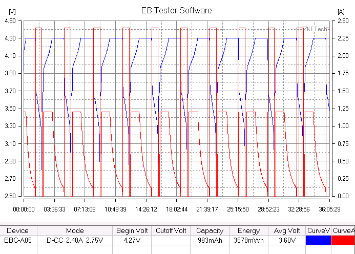
The problem can be seen in this chart.2015-2-12-10-14-45-EBC-A05

The charge phase is supposed to terminate when the current, shown in red, hits 0.12 A. Instead, it terminates at ~0.25A in the first cycle, and at ~0.5A in subsequent cycles.

I realized that the subsequent cycles were also terminating at about 90 minutes, which stood out, because I’d set a 90 minute timer for terminating the discharge phase if the voltage didn’t drop below a threshold first. A check of the raw data showed that the termination happened at ~88 minutes.

The device doesn’t allow a timer to be set during the charging phase, but I hypothesized that the timer from the previous discharge phase was somehow being utilized during the charging phase. I tried shortening and lengthening the discharge timer and found that, as I expected, it had a corresponding impact on the length of the charging cycle.

So, the workaround is to either omit the timer on the discharge phase, or set it to a duration larger than the time required to achieve a full charge for the cell under test. I’ve successfully run dozens of cycles now:

2015-2-19-11-2-0-EBC-A05

I also reported my findings to ZKE, using their published email address and received a reply thanking me for the report and letting me know that they would have an updated firmware by the end of the month.

ZKE EBC-A05 Cycle Testing Anomaly

I didn’t do much with my ZKE EBC-A05 battery tester last week while I waited for a cheap, small used PC to arrive to run the EB Test software for long-term tests.

The computer came earlier this week, and after getting Windows patched up, I set up a test to run overnight that would cycle between charging to 4.3v and 0.12A, pausing, discharging at 2.4A to 2.75v, waiting 10 minutes for the cell to cool down, and then repeating the cycle.

When I checked on the progress this morning, everything looked good at first glance.

2015-2-12-10-14-45-EBC-A05Upon closer inspection though, I noticed that after the first charging cycle proceeded until 4.3v but terminated prematurely, at  0.25A current, and subsequent cycles cut of prematurely, at ~0.5A.

I tried stopping the test and restarting it again, and found that this time, the first charging cycle terminated at 0.5A.

I’ve powercycled the EBC-A05 and started a new testing cycle. So far, so good, the first charging cycle terminated at 0.12A, as desired. We’ll see if that holds for subsequent cycles.

I must say though, the fact that I’ve had this problem once makes me less enthusiastic about this device.  I was thinking of buying another 3, so I could run duplicate control and experimental runs of multi-day experiments at a time, but that only makes sense if these things are generally reliable.

5000 mAh Apple, I mean Millet, I mean Xiaomi USB Power Bank

Finally received a new Apple USB Power Bank I ordered 3 weeks ago.

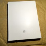
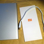
Did I say Apple?  I mean, Millet, no, sorry, Xiaomi. Sorry for the confusion, but in my defense, Xiaomi is borrowing so much of Apple’s design language, from the satin white packaging, to the specific grey of the logo and the “swiss” typeface, not to mention the particular tone and finish on the aluminum case.

I got the 5,000 mAh hour version from Banggood for $15.99, shipped. It took a three weeks to get here, but arrived in good condition. The footprint is about the size of my iPhone 6’s, but the powerbank is almost twice as thick.

It doesn’t quite achieve the fit-and-finish of an Apple product, but it definitely feels well made. That general level of quality is more than skin deep too.

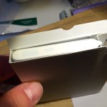
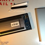
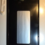
The plastic trim pieces at either end of the case are secured with a few locking tabs and double-sided tape. It takes some delicacy but prying off the plastic trim on the bottom end reveals two phillips head screws. Removing them allows another plastic plate to be removed, which allows the core, holding the battery and the circuit board to slide out easily.

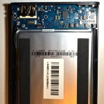
The PCB is populated with surface mount components, including a very nice, highly integrated BQ24195 IC from Texas Instruments that is well suited for power bank use. This chip does double-duty, providing both a buck-converter based lithium ion charger and a highly efficient boost-converter to provide the 5V necessary for USB devices from the battery. Both functions share the same shielded inductor, and operate at 1.5MHz, providing >90% efficiency during both charging and discharging. This efficiency makes the most of the power in the battery, but in doing so, it also reduces heat generation, allowing the pack to be charged at up to 2A. Discharge current is up to 2.1A. My brief testing bears out these numbers.

The power bank also has a thermistor, allowing the power IC to monitor the temperature of the cell during charge and reduce the charging current to prevent overheating. I’d guess it also uses the ICs ability to limit charging current draw based on USB coding from the input source.

This chip can be microprocessor controlled, and the microprocessor can set the charging voltage and current. I’m sure this comes in handy for Xiaomi, allowing them to swap in cells with different charge termination voltages without having to change components. Xiaomi also uses similar chips in their larger power banks.

I’m thinking of looking into getting ICs made up into small modules that can be incorporated into DIY projects. They support input voltages up to 17v, charging currents up to 4.5A. The boost-converter output current is apparently limited to 2.1A, but that’s still pretty good, and the IC can provide discharge protection at battery voltage at up to 6A sustained.

The pouch cell in my example comes from Lishen, but other teardowns have cells from ATL, which reviewers have conspicuously noted, also supplies cells to Apple.

I haven’t put this through a full cycle of use or tests, but based on the reports of others, I expect this to be a capable USB power bank.

Test Results for LG INR18650-MJ1 3,500mAh 18650 Li-ion Battery

Recently, there was news of LG’s first lithium nickel cobalt aluminum oxide chemistry cells. Panasonic has long led the market for 18650 Lithium Ion batteries with their own cells based on that chemistry. Their NCR18650B at 3,350 mAh capacity has been in wide availability for the last year, and some of their 3,600mAh NCR18650G’s have also popped up.

We now have reports of the highest capacity 3,500mAh INR18650-MJ1 version of LG’s new cells in the wild. If the real-world examples match LG’s claims, Panasonic will have some serious competition.

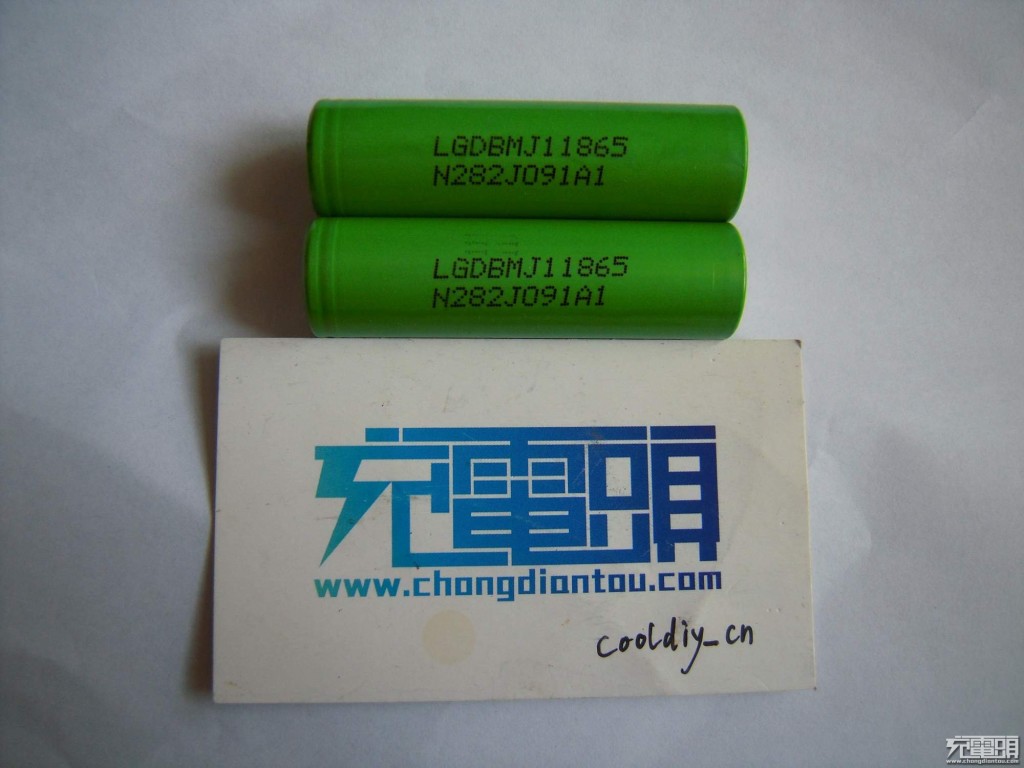
194009wqt7itir7g7i5tmu

Lucky for all of us, cooldiy_cn managed to get his hands on two of these cells and ran them through a series of tests which he posted on the Chinese Chongdiantou forum.

The weights of his two examples were 46.60g and 46.65g.

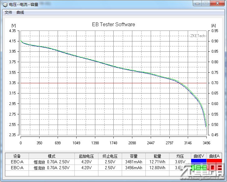
LG INR18650-MJ1 0.5C Discharge Curve

Above, you can see the test results with a 0.2C/0.7A discharge from 4.2v to 2.5v, which delivered 3,481 & 3,496 mAh.

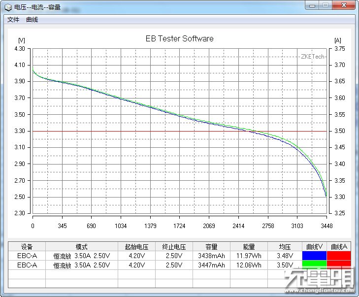
INR18650-MJ1 3.5A discharge

At 1C/3.5A usable capacity is only diminished by about 1% and usable capacity remains good at higher discharge rates.

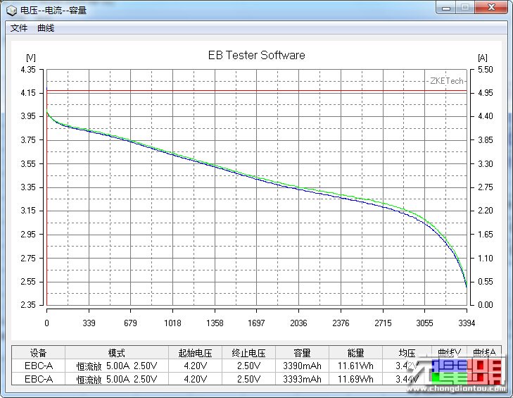
LG INR18650-MJ1 5A Discharge Test

At 5A, usable capacity is 3,390 and 3,393 mAh, or ~97% that delivered at 0.2C/0.7A.

LG INR18650-MJ1 10A Discharge

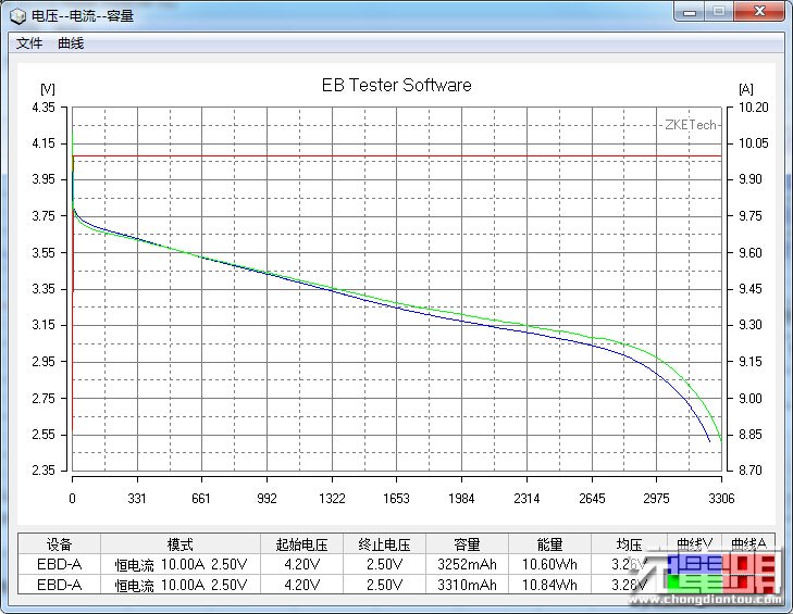
10A discharge is 3,252 and 3,310 mAh, or ~95% the usable capacity at a 0.2C/0.7A discharge.

He also tested the internal resistance of his two cells, and found that they were about 28mOhm (caveat that this can vary depending on method of measurement).

All in all, this is a promising development. I look forward to being able to buy these in new-old-stock and lightly used laptop packs, in a few years.