Overview
PackProbe is an Arduino-based solution for reading useful Smart Battery System information from laptop batteries without requiring the corresponding model of laptop.
Quick link: Battery connection pinouts and advice
Prerequisites
- The understanding that you are responsible for educating yourself on the risks of dealing with power supplies like Lithium Ion battery packs.
- Basic electrical and electronics knowledge
- Computer with the Arduino IDE
- Arduino compatible board
- Suitable communicaitons cable and drivers for your board
- Small breadboard
- Jumpers/Hook-up wire.
- 2x 10K Ohm resistors
- Multimeter (optional, but very useful)
- Low-current 6-9v DC powersource (9v battery will work)
Obtaining PackProbe
Download the latest version of the PackProbe sketch and dependencies:
- Download the latest version of PackProbe or clone the Github Respository
- Download the SoftI2CMaster library
Arduino Environment
Prepare your Arduino hardware and software. If you aren’t already familiar with the Arduino hardware and software environment, you should refer to the Arduino Getting Started documentation.
- Locate your Arduino folder
- Macintosh OS X: ~/Documents/Arduino/
- Windows: My Documents\Arduino\
- Unzip the SoftI2CMaster library and move the folder to your Arduino/libraries folder.
- Unzip the PackProbe sketch you downloaded and move it to your Arduino folder.
- Connect your Arduino
Configure Board
PackProbe is currently distributed configured for use with the WiFi-enabled Arduino Yun. If you are using it with another board, you’ll have to manually edit the sketch for your board. You will also have to edit the sketch to use Serial output.
More information on configuring the pin mappings and output method follow. There are also comments in the source code to help you find all the sections you’ll need to edit.
Pin Mapping
As distributed, PackProbe connects to the smart battery over SMBus/I2C via DigitalPin 6 for data, and DigitalPin 8 for the clock connection when used with an Arduino Yun or Leonardo.
If you are using PackProbe with a different board, or you want to use different pins, you will need to figure out the pin-mapping of your board and make the necessary edits the PackProbe sketch.
- SoftI2CLibrary Documentation
- Port Manipulation Overview
- Atmega 168/328 MCU (Uno, Mini, Nano, Fio, Pro)
- Atmega 32u4 MCU (Yun, Leonardo, Micro)
The necessary changes are confined to the top of the sketch.
Output Method
As distributed, PackProbe’s output is sent to the Arduino Yun’s Console, which is accessable via ssh, or the “Serial Monitor” in the Arduino IDE.
If you are using PackProbe with a different board, you’ll have to make multiple edits to the PackProbe sketch:
- Change the sketch to replace “#include <Console.h>” with “#include <Serial.h>”, or whatever serial port is most appropriate for your Arduino hardware.
- Comment out the “Bridge.begin()” and “Console.begin()” statements.
- Uncomment the statements that initialize the serial connection, and edit them to refer to whichever serial port you chose above.
- Replace all references to “Console.” (ie Console.print, Console.write) with the appropriate reference to the serial port you chose above (ie Serial.print, Serial.write)
I’d like to make this choice easier with sensible defaults for common Arduino boards. If you get to it first, code contributions are welcome!
Check and Upload
- After installing the sketch and library, and making any necessary changes, use the arduino IDE to check your sketch.
- If you get errors, refer to the Arduino documentation for troubleshooting tips.
- Once your sketch checks out, you can load it onto your board.
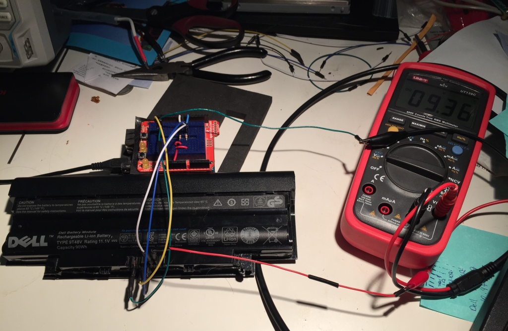
Connection Circuit
The added circuitry required to connect your Arduino to your battery pack is relatively straightforward.
- connect data and clock pins (configured above) via the 10K Ohm pull-up resistors to the 5V pin on your board.
- If you are using a board that isn’t 5V tolerant, and doesn’t supply 5V, you can use the 3.3V pin, but you may need to use a correspondingly smaller resistance value for the pull-up.
Pack Connection
Before connecting to the battery pack, you should educate yourself on the risks of lithium ion batteries, including but not limited to:
- The potential for damaging the electronics of the pack, your Arduino, or even if your computer if you wire things incorrectly.
- The potential for burns or even fire in the event of a low-reistance connection between the positive and negative terminals of the battery pack.
With that warning in mind:
- Once you have the pull-ups connected to to the 5V supply, you can connect to the pack. The exact pinout of the connectors vary from manufacturer, and even amongst models from the same manufacturer.
- We provide pinouts for packs we’ve encountered, and advice on figuring out pinouts for unknown packs. You should verify any provided pinouts with a multimeter in order to avoid damage to your equipment. Contributions are welcome.
Quick link: Battery connection pinouts and advice
Obtaining Data
Upon installation, power-up, or reset, the sketch waits for a connection to the console or serial port before trying to talk to the battery pack.
Once the connection is made, the sketch scans through device addresses and then tries to read the desired data from the attatched pack.
If the pack is connected properly and functioning, you should see an “Ok” for device address 0xB (11) during the initial address scan.
If you don’t see an “Ok” then you may need to connect the packs “battery enable” pin to ground with a ~500 Ohm resistor.
If your pack doesn’t have a Battery Enable pin and/or it still doesn’t respond when you connect it, you may need to “jumpstart” the pack by applying 9v across the positive and negative terminals (make sure the polarity matches that of the pack, ie negative to negative, positive to positive). You may want to use diodes to prevent current flowing back into your power source. Often times, the pack will immediately spring to life and you’ll see useful values in the console output. If you don’t, you can reset the Arduino to make the sketch scan the bus again. Once a pack is “awake,” some packs will continue to provide data even after the jumpstart voltage and/or the battery enable connection is removed, provided the pack voltage is above a safety threshold (often ~9v for packs with 10.8-11.1v nominal voltage).
If you see an Ok, but the pack information is gargbage (-1 or -2), then there is another issue. So far, we’ve seen the issue with HP TD06 packs and Samsung packs we’ve tested. We don’t yet know what the problem is, and would appreciate hearing from anyone who has success using PackProbe with HP or Samsung packs.
Interpreting the Output
Most of the output is pretty self-explanatory. Some of the most useful information is also the easiest to understand.
Manufacture Date indicates the age of the pack, and by extension the cells which were probably packed soon after manufacture. Cells gradually loose capacity from the time they are manufactured. Older cells might not be suitable for the most demanding applications, but we’ve seen unused 5-year old cells that still provide excellent capacity and power.
Cycle Count indicates how much use pack has seen. Cells loose a little capacity each time they are recharged. I’ve heard that typically manufacturers design packs to provide ~80% of their original rated capacity after 300 charge cycles. Whether or not a pack is worth your time and energy is your decision to make. We tend to view packs with 75 cycles or less as being relatively fresh, while packs with 250 or more cycles are at risk of being worn out.
Later versions of PackProbe will make it easy to contribute pack data to a central database that we’ll use to provide better estimates of cell vitality and better guidelines for cell reuse.
Voltage, reported in millivolts, can give a hint about the health of the cells inside. Anything lower than 6v for a 3S pack (3 banks of cells in series, 10.8-11.25v nominal voltage), or 8v for a 4S pack (14.1 – 14.8v nominal voltage) indicates at least some of the cells are discharged below safe levels.
Cell voltages are also reported for each parallel bank of cells, though the data will be incorrect if the pack doesn’t support the functions PackProbe uses to retrieve this data. This information gives further insight into the health of the cells beyond the overall pack voltage, and can show when a low pack voltage is caused by low voltage in a subset of the cells, rather than all of them.
The number of banks of cells can be guessed based on the nominal voltage of the pack.
- 7.2-7.4v: 2 banks
- 10.8-11.35v: 3 banks
- 14.4 -14.95v: 4 banks
If a pack is compatible with PackProbe’s cell voltage reporting function and has less than 4 banks, it will report 0mV for banks that aren’t present.
The reported voltage for Cell1 – Cell4 will generally be between 2000 mV and 4200mV. Voltages between 0 and 2000 mV may indicate over-discharged cells, or may be a hint of incompatibility between the functions PackProbe uses to retrieve this data, and the pack. If negative voltages, or voltages over 5000mV are reported, that is a strong sign of incompatibility. If any cells report voltage in this range, its is an indicator that reasonable looking voltages reported for other cells are incorrect.
If you decide a pack is worth dissecting, you should verify the voltage of each cell you remove before charging.
PackProbe also retrieves and reports information about the original and current capacity of the battery pack, as well as diagnostic information about the health and state of the pack. At this stage of PackProbe’s development, this information, shouldn’t be considered reliable, due to nuances and ambiguities we haven’t worked through yet. One specific issue is that, some packs default to reporting capacity and charge remaining in mAh, while others use Wh.
For more information about Smart Battery Data:
Next Steps
- Contribute data / results in comments
- Tear apart your pack
- Charge cells
- Dispose of bad cells/packs using the EWaste recycling available in your community.
Hi,
I only read -1, In a new attempt, I tried change the plus operation by OR operation like arduino website means..
i2c_start((deviceAddress<<1) | I2C_WRITE);
i2c_rep_start((deviceAddress<<1) | I2C_READ);
and the scketch work fine now !!
(sorry, I'm not a native speaker)
Thanks so much
Hi and thanks for the code. I have succeeded to read data from a Lenovo Z70 battery.
The battery had only 2 cycles of recharge and after that had self discharged in time (2 years) on a shelf inside the laptop.
Now i have opened the pack and manual charge the cells, because the chip (BQ30695A) reported as faulty and set a flag in memory as “not chargeable”.
The cells are actually very good (tested – full capacity).
All i need now is to access this memory flag and reset it somehow.
If anyone knows how to do this i will be thankful.
It looks like i need to write a 4 bytes key pass to address 0x00 (ManufacturerAcces) to get access to 0x53 (PermanentFailureFlag) and reset this flag.
Example for BQ20Z80 chip Permanent Failure reset:
by sending 4 bytes to 0x00 : 1st two bytes 0x2673 and 2nd two bytes 0x1712.
The key pass is proprietary to Lenovo or Texas Instruments.
I have experience in electronics and reverse engineering for over 15 years of work, but it’s not worth the time spent for getting this fixed.
I just bought a new battery, to bad that in Romania where i live, i find only chinese compatible batteries, no original ones.
Lenovo and Texas Instruments maybe makes this batteries with a short life for us to buy new ones, but in the end only black market get the money in some countries 😉
Thanks for all.
Great project! please guide how to Permanent Failure reset in bq30z55 chip cheers!